5. Power Supply Finite State Machine
The behaviour of the power unit output is determinated by a Finite State Machine (FSM).
The Output Finite State Machine is the following:
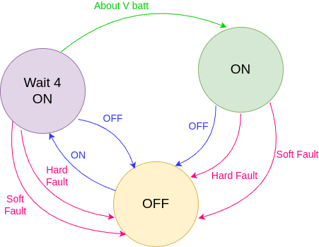
The three FSM states are:
OFF State: in this state the output drivers and PID controller are disabled. This is the default state at machine startup.
- ON State: in this state the output drivers and PID controller are enabled and the unit can accepts a new setpoint. The default setpoints are:
0A in CC Mode
Battery Voltage in CV Mode
Wait for On State: in this state the unit sets internally the output to the battery voltage with the output disconnected. When the output reaches the battery voltage, the FSM evolves automatically to ON State.
The transition between the states are the following:
Command-related transitions (in blue): that are defined by software commands (see OUT Command)
Fault-related transitions (in red): that are defined by a Fault condition. When a fault occurs, the machine starts a transition to a “safe state”, this is the OFF State in which the power stage is disabled.
- There are two types of Fault conditions:
Soft Fault: faults that does NOT impact the functionality of the power unit (for example a temperature fault).
Hard Fault: faults that impact directly the correct functionality of the power unit (for example a DCCT fault).
Internal transitions (in green): there is only one internal transition that is related to the output voltage. This transition is used only when the OUT FSM is in OUT Wait for On State and the output reaches the battery voltage, at this point the OUT FSM automatically evolves to OUT ON State.